Here is the simple topology for this lab. R1 and R2 are on VLAN 12. VLAN12 needs to be IPv6 only. We test this my assigning IPv4 and IPv6 addresses to both routers and then pinging.
R1---SW1---SW2---R2
R1:
IPv4: 192.168.12.1/24
IPv6: 2001::1/64
R2:
IPv4: 192.168.12.2/24
IPv6: 2001::2/64
Making a vlan IPv6 only requires more configuration than I previously thought. This was my first attempt. On all switches:
mac access-list extended IPv6
permit any any 0x86DD 0x0
vlan access-map IPv6only 10
action forward
match mac address IPv6
vlan filter IPv6only vlan-list 12
So R1 pings R2:
R1#ping 192.168.12.2
Type escape sequence to abort.
Sending 5, 100-byte ICMP Echos to 192.168.12.2, timeout is 2 seconds:
.....
Success rate is 0 percent (0/5)
R1#ping 192.168.12.2
But wait, let's remove the filter, ping, add the filter back, and ping again.
SW1(config)#no vlan filter IPv6only vlan-list 12
R1#ping 192.168.12.2
Type escape sequence to abort.
Sending 5, 100-byte ICMP Echos to 192.168.12.2, timeout is 2 seconds:
!!!!!
Success rate is 100 percent (5/5), round-trip min/avg/max = 1/3/4 ms
SW1(config)#vlan filter IPv6only vlan-list 12
R1#ping 192.168.12.2
Type escape sequence to abort.
Sending 5, 100-byte ICMP Echos to 192.168.12.2, timeout is 2 seconds:
!!!!!
Success rate is 100 percent (5/5), round-trip min/avg/max = 1/2/4 ms
R1 can still ping. What happened? Well the original filter wasn't blocking IP, it was only blocking ARP packets. Remember MAC access-lists do not have an implicit deny for the IP ethertype but they do have an implicit deny for all the other ethertypes. So once we removed the filter and allowed ARP through, R1 was able to ping R2 when the filtered was applied.
To make the vlan IPv6 only I had to specify a drop action in an empty access-map statement:
SW1(config)#vlan access-map IPv6only 20
SW1(config-access-map)# action drop
R1#ping 192.168.12.2
Type escape sequence to abort.
Sending 5, 100-byte ICMP Echos to 192.168.12.2, timeout is 2 seconds:
.....
Success rate is 0 percent (0/5)
R1#
But wait, let's check out spanning-tree:
SW1#sho spanning-tree vlan 12 | inc root
This bridge is the root
SW2#show spanning-tree vlan 12 | inc root
This bridge is the root
This is bad because both switches forward out all ports when they think they are root. If we had multiple links between these switches, we would have a loop. You may start seeing these messages:
SW2#
01:28:49: %SW_MATM-4-MACFLAP_NOTIF: Host 00b0.6410.3901 in vlan 12 is flapping between port Fa0/13 and port Fa0/14
01:28:49: %SW_MATM-4-MACFLAP_NOTIF: Host 0007.eb14.4f81 in vlan 12 is flapping between port Fa0/13 and port Fa0/14
We need to allow STP bpdu's in our original MAC access-list. Do this now:
SW1(config)#mac access-list extended IPv6
SW1(config-ext-macl)#permit any any lsap 0xAAAA 0x0
Now we see SW2 blocking on the port f0/14 (for VLANs 1 and 12):
SW2#sho span | inc BLK
Fa0/14 Altn BLK 19 128.16 P2p
Fa0/14 Altn BLK 19 128.16 P2p
Verify R1 can ping R2 via IPv6 and not IPv4:
R1#ping 192.168.12.2
Type escape sequence to abort.
Sending 5, 100-byte ICMP Echos to 192.168.12.2, timeout is 2 seconds:
.....
Success rate is 0 percent (0/5)
R1#ping 2001::2
Type escape sequence to abort.
Sending 5, 100-byte ICMP Echos to 2001::2, timeout is 2 seconds:
!!!!!
Success rate is 100 percent (5/5), round-trip min/avg/max = 0/1/4 ms
R1#
I used 0xAAAA because this what lsap type PVST uses. I don't know where I got this but I think I saw it on GS somehwere. I have also seen 0x4242 used but I think this is for normal STP (802.1d). In any case, only the 0xAAAA worked for me.
Tuesday, December 23, 2008
Monday, December 22, 2008
Extended Range VLAN - FAIL
I was reading an old post on CCIE talk about extended range vlans and I learned something new. The post is here: CCIE Talk
If a Catalyst switch has any routed ports then it uses an extended vlan as an "internal vlan" for that port. Why? I don't know but it's something to take caution with if you run into any issues.
Check it out:
SW1#sho vlan internal usage
VLAN Usage
---- --------------------
Now let's create a routed port:
SW1(config)#int f0/24
SW1(config-if)#no sw
Now we have VLAN 1006 taken up:
SW1#sho vlan internal usage
VLAN Usage
---- --------------------
1006 FastEthernet0/24
SW1#
What happens if we try to create or modify VLAN 1006? Let's see:
SW1(config)#vlan 1006
SW1(config-vlan)#exit
% Failed to create VLANs 1006
VLAN(s) not available in Port Manager.
%Failed to commit extended VLAN(s) changes.
00:06:13: %PM-4-EXT_VLAN_INUSE: VLAN 1006 currently in use by FastEthernet0/24
00:06:13: %SW_VLAN-4-VLAN_CREATE_FAIL: Failed to create VLANs 1006: VLAN(s) not available in Port Manager
SW1(config)#
FAIL. What if we were supposed to use VLAN 1006? Shut it down, enable VLAN 1006, then re-enable the port.
SW1(config)#int f0/24
SW1(config-if)#shut
SW1(config)#do show vlan internal usa
VLAN Usage
---- --------------------
SW1(config)#vlan 1006
SW1(config-vlan)#exit
SW1(config)#int f0/24
SW1(config-if)#no shut
SW1(config-if)#exit
SW1(config)#do show vlan internal usa
VLAN Usage
---- --------------------
1007 FastEthernet0/24
The switch uses the next number.
Friday, December 19, 2008
IP Source Guard
I was reading through the 3560 Configuration guide looking for things to lab and I came up with this. I already had DHCP snooping configured from my last lab so it was real easy.
Topology:
R1---SW1---R3
R1 has an address via DHCP:
R1#show ip int brief | ex unas
Ethernet0/0 192.168.12.1 YES DHCP up up
R1 can ping R3 on it's subnet:
R1#ping 192.168.12.3
Type escape sequence to abort.
Sending 5, 100-byte ICMP Echos to 192.168.12.3, timeout is 2 seconds:
.!!!!
Success rate is 80 percent (4/5), round-trip min/avg/max = 1/3/4 ms
Sw1 has dhcp snooping already enabled. Here we configure IP source guard:
SW1(config)#int f0/1
SW1(config-if)#ip verify source
Now on R1 if we change the IP address, we cannot ping anymore:
R1(config)#int e0/0
R1(config-if)#ip address 192.168.12.100 255.255.255.0
R1(config-if)#^Z
R1#ping 192.168.12.3
Type escape sequence to abort.
Sending 5, 100-byte ICMP Echos to 192.168.12.3, timeout is 2 seconds:
.....
Success rate is 0 percent (0/5)
Verify IP source guard is in effect on SW1:
SW1#show ip verify source
Interface Filter-type Filter-mode IP-address Mac-address Vlan
--------- ----------- ----------- --------------- -----------------
Fa0/1 ip active deny-all 12
Set R1 to get address via DHCP:
R1(config)#int e0/0
R1(config-if)#ip address dhcp
*Mar 1 02:53:06.259: %DHCP-6-ADDRESS_ASSIGN: Interface Ethernet0/0 assigned DHCP address 192.168.12.4, mask 255.255.255.0, hostname R1
Now R1 can ping again:
R1#ping 192.168.12.3
Type escape sequence to abort.
Sending 5, 100-byte ICMP Echos to 192.168.12.3, timeout is 2 seconds:
.!!!!
Success rate is 80 percent (4/5), round-trip min/avg/max = 1/3/4 ms
Verify on SW1:
SW1#show ip verify source
Interface Filter-type Filter-mode IP-address Mac-address Vlan
--------- ----------- ----------- --------------- -----------------
Fa0/1 ip active 192.168.12.4 12
You can also configure static bindings, but I will probably do that in another blog :)
Wednesday, December 17, 2008
SLA - Sending a Constant Bitrate
Everytime I study QoS I think about ways to generate a constant rate of traffic from a router. I always test using pings but I never really know at what rate data is being pushed through. With SLA, I can configure a somewhat rudimentary way of doing this.
Suppose I want a router R1 to send 64K to R7 (off in the distance).
Let's figure out the data size and frequency. There are probably multiple ways to do this depending on frequency and request-data-size but here is how I do it:
My load-interval on R7 is going to be 30 seconds so 1,920,000 (64,000 x 30) bits need to flow through every 30 second interval. Now if I send data a 1 second intervals, then I need to send 64000 bits every second. 64000 bits = 8000 bytes.
Formula using 1 second frequency intervals:
Load-interval X desired bitrate = total bits per interval
total bits per interval / 8 = request-data-size
Here is the config:
R1(config)#ip sla monitor 1
R1(config-sla-monitor)#type echo protocol ipIcmpEcho 150.100.56.7
R1(config-sla-monitor-echo)#request-data-size 8000
R1(config-sla-monitor-echo)#frequency 1
On R7 I created this tracker:
ip sla monitor responder
access-list 100 permit icmp host 150.100.12.1 any
class-map match-all SLA
match access-group 100
policy-map TRACK-SLA
class SLA
interface FastEthernet0/0
service-policy input TRACK-SLA
Now Let's start the SLA monitor on R1:
R1(config)#ip sla monitor schedule 1 life forever start-time now
Now on R7 we use the show policy-map interface command to see the bit rate. It takes a little while but it should peak near 64000 bps give or take 1000.
After 750 packets we have 65K:
R7#sho policy-map interface
FastEthernet0/0
Service-policy input: TRACK-SLA
Class-map: SLA (match-all)
750 packets, 1027500 bytes
30 second offered rate 65000 bps
Match: access-group 100
Class-map: class-default (match-any)
91 packets, 6548 bytes
30 second offered rate 0 bps, drop rate 0 bps
Match: any
Now several minutes later we are still at 65K:
R7#sho policy-map interface
FastEthernet0/0
Service-policy input: TRACK-SLA
Class-map: SLA (match-all)
2784 packets, 3814080 bytes
30 second offered rate 65000 bps
Match: access-group 100
Class-map: class-default (match-any)
280 packets, 20188 bytes
30 second offered rate 0 bps, drop rate 0 bps
Match: any
Parser View
I was reading this pdf called "1001 things to do with a Cisco Router" and I came across this topic. I have done it before while doing the ISCW but here it is again.
FIRST, ENABLE AAA:
R4#conf t
Enter configuration commands, one per line. End with CNTL/Z.
R4(config)#aaa new-model
SET ENABLE PASSWORD:
R4(config)#enable secret cisco
R4(config)#^Z
SWITCH TO VIEW MODE:
R4#en view
Password:
R4#
*Mar 2 23:03:20.352: %PARSER-6-VIEW_SWITCH: successfully set to view 'root'.
R4#
NOW WE CAN CREATE THE VIEW:
R4(config)#parser view operator
R4(config-view)#?
View commands:
commands Configure commands for a view
default Set a command to its defaults
exit Exit from view configuration mode
no Negate a command or set its defaults
secret Set a secret for the current view
R4(config-view)#commands exec include ping
% Password not set for the view operator
R4(config-view)#secret operator
R4(config-view)#commands exec include ping
R4(config-view)#commands exec include show hardware
R4(config-view)#commands exec include show interface
R4(config-view)#commands exec include show ver
R4(config-view)#exit
LOG IN TO THE VIEW:
R4#en view operator
Password:
*Mar 2 23:05:41.212: %PARSER-6-VIEW_SWITCH: successfully set to view 'operator'.
R4#show ?
flash: display information about flash: file system
hardware Hardware specific information
interfaces Interface status and configuration
parser Display parser information
slot0: display information about slot0: file system
slot1: display information about slot1: file system
version System hardware and software status
ALSO, YOU CAN ADD THE VIEW TO THE USER:
R4(config)#username operator view operator password operator
Monday, December 15, 2008
DHCP Snooping - missing command?
I was having a hard time with this awhile ago because I could not get an address even when I enabled "trust" on the server port. However, after looking through the PG on Mock Lab 3 and discussion in the cisco channel on freenode I found out the issue.
I needed this command on the server:
R2(config)#int e0/0
R2(config-if)#ip dhcp relay information trusted
Now my binding database is populated after about 9 months!
SW1#show ip dhcp snooping binding
MacAddress IpAddress Lease(sec) Type VLAN Interface
------------------ --------------- ---------- ------------- ---- --------------------
00:07:EB:14:4F:81 192.168.12.1 86312 dhcp-snooping 12 FastEthernet0/1
Total number of bindings: 1
SW1#
Sunday, December 14, 2008
IPexpert Volume 3 Mock Lab 3 Review
I finished this lab in a little more than 6 hours. It was a graded lab through Proctor Labs and I got an 82. This a very challenging lab because there was some dot1q tunneling involved and it affected reachability if you didn't prune VLANs properly due to l2portguard errors. Also, there was an IPv6 tunneling section which I got right. In fact, I got 100% on IGP, BGP and Multicast for a total of 44 points.
Here are the mistakes I made:
-3 1.2 Switching
Did not enable trust on the trunk ports after I enabled DHCP snhooping.
-2 2.3 Frame Relay
After I did some NAT R4 could no longer ping R2 over the Frame-relay.
-3 6.1 VRRP
I used group 1 instead of group 24. BONEHEAD mistake.
-4 6.5 IOS Services
Some NAT stuff. I think I got this right but...oh well.
-3 8.1 QoS
PBR config was supposedly on the wrong interface. I am arguing this one with the script writers.
-3 9.2 Security
I got the URL string wrong for blocking NIMDA.
All in all I felt pretty good. I had been practicing tunneling last night and I don't think I would have done as well or finished as fast if I hadn't. I gained a lot of confidence this round. There were some things I did not think I would be able to figure out upon the initial read-through. However, once I turned off the TV, I was in a pretty good groove :-)
Saturday, December 13, 2008
IPexpert Volume 2 Section 13 Reveiw - Part II
I just finished the lab that I started last week. I don't really have an estimate of how well I did because I had several conflicts with the PG. My guess is around 70 - 80. It was definitely the hardest full scale practice lab I have done to date. Not so much in configuration, just in understanding what the PG was trying to say. Here are some examples:
R2 should show L2 circuit IDs when viewing "debug traces." This was in the security section and the answer was to create an ACL that permitted everything and log-input for ICMP. Easy enough and I thought about that solution but I thought there might have been another way - alas, there wasn't.
CAT1 should only allow PC with mac address 0001.0001.0001 and IP 10.10.10.1 on port f0/10. I thought about ARP inspection along with port security but the answer was only port security. Not sure if I would gotten it wrong if I had the port security right but borked on the ARP inspection which was not required.
There was also an auto-command task that forced me to override what I had already configured for my VTY lines in previous tasks. I would have had to ask the proctor about this as there was no way to have the two solutions (line password and local authentication) without AAA. And my AAA solution was not allowing auto-command to work.
There was a total of 58 tasks on this lab which is incredible because I don't think I have had a lab that had as many as 40 yet. Each task was 1 or 2 points and there was a lot to configure. I don't know if I would have completed it in 8 hours - I took my time writing emails to support during the lab.
In any case, this was a very challenging lab and I think I will re-do this one in a couple months if I have time.
Auto-install, eh?
While doing IPexpert Volume 2 Section 13 I ran into a task that said:
"There is a high chance you will be replacing your current R4 router with another high-end router. The admin of R4 has saved its configuration on a TFTP server whose IP address is 136.10.12.100. Make sure the new router will automatically configure itself."
So I started browsing through the DocCD for auto-install when it hit me...how exactly is this supposed to work? Not knowing the exact details about auto-install I knew that this should be a simple task since it was only 1 point.
Well the new router needs to know about address 136.10.12.100 somehow...but when it has no config it has no address. What I figured was that the new router will send a broadcast on it's frame-relay interface which happens to connect to R2. In fact the 136.10.12.100 network is also on R2's ethernet interface.
So I configured a helper address on R2's frame-relay interface pointing to 136.10.12.100. The PG agreed! 1 task, 1 command, 1 point :-)
Thursday, December 11, 2008
ECMP Multicast Load Splitting
This is a pretty simple concept. By default when two paths to the RP exist, the router sends a join to the one with the highest IP address. When you enable multicast multipath, the router will send joins up multiple paths depending on Source address (this hash is modifiable in some IOS)
Here is the topology:

R4 has joined group 239.0.0.1. R5, R6 and R7 are all sending pings to this address. Before enabling multipath, this is what R1's mroute table looks like (it's actually bigger I am omitting output for the sake of brevity):
R1#show ip mroute | be \(
(*, 239.0.0.1), 00:00:09/stopped, RP 2.2.2.2, flags: SJC
Incoming interface: Serial1/3, RPF nbr 150.100.21.2
Outgoing interface list:
FastEthernet0/0, Forward/Sparse, 00:00:09/00:02:50
(6.6.6.6, 239.0.0.1), 00:00:07/00:02:58, flags: JT
Incoming interface: Serial1/3, RPF nbr 150.100.21.2
Outgoing interface list:
FastEthernet0/0, Forward/Sparse, 00:00:07/00:02:52
(150.100.56.5, 239.0.0.1), 00:00:05/00:02:58, flags: JT
Incoming interface: Serial1/3, RPF nbr 150.100.21.2
Outgoing interface list:
FastEthernet0/0, Forward/Sparse, 00:00:05/00:02:54
(150.100.56.6, 239.0.0.1), 00:00:07/00:02:58, flags: JT
Incoming interface: Serial1/3, RPF nbr 150.100.21.2
Outgoing interface list:
FastEthernet0/0, Forward/Sparse, 00:00:07/00:02:52
(150.100.56.7, 239.0.0.1), 00:00:10/00:02:57, flags: JT
Incoming interface: Serial1/3, RPF nbr 150.100.21.2
Outgoing interface list:
FastEthernet0/0, Forward/Sparse, 00:00:10/00:02:49
Notice that it has sent joins only on Serial 1/3. Thus, R2 only sends multicast traffic for 239.0.0.1 out of this interface. R2 OIL looks like this:
R2#show ip mroute 239.0.0.1 | sec Outgoing
Outgoing interface list:
Serial1/3, Forward/Sparse, 00:34:58/00:02:44
Outgoing interface list:
Serial1/3, Forward/Sparse, 00:13:39/00:02:44
Outgoing interface list:
Serial1/3, Forward/Sparse, 00:13:39/00:02:46
Outgoing interface list:
Serial1/3, Forward/Sparse, 00:13:39/00:02:45
Let's enable multicast multipath on R1:
R1(config)#ip multicast multipath
Now we can see Joins have been sent out of both interfaces:
R1#show ip mroute | be \(
(*, 239.0.0.1), 00:00:01/stopped, RP 2.2.2.2, flags: SJC
Incoming interface: Serial1/3, RPF nbr 150.100.21.2
Outgoing interface list:
FastEthernet0/0, Forward/Sparse, 00:00:01/00:02:58
(6.6.6.6, 239.0.0.1), 00:00:01/00:02:58, flags: JT
Incoming interface: Serial1/3, RPF nbr 150.100.21.2
Outgoing interface list:
FastEthernet0/0, Forward/Sparse, 00:00:01/00:02:58
(150.100.56.5, 239.0.0.1), 00:00:01/00:02:58, flags: J
Incoming interface: Serial1/2, RPF nbr 150.100.12.2
Outgoing interface list:
FastEthernet0/0, Forward/Sparse, 00:00:01/00:02:58
(150.100.56.6, 239.0.0.1), 00:00:01/00:02:58, flags: JT
Incoming interface: Serial1/3, RPF nbr 150.100.21.2
Outgoing interface list:
FastEthernet0/0, Forward/Sparse, 00:00:01/00:02:58
(150.100.56.7, 239.0.0.1), 00:00:00/00:02:59, flags: J
Incoming interface: Serial1/2, RPF nbr 150.100.12.2
Outgoing interface list:
FastEthernet0/0, Forward/Sparse, 00:00:00/00:02:59
R2's OIL now looks like this:
R2#show ip mroute 239.0.0.1 | section Outg
Outgoing interface list:
Serial1/3, Forward/Sparse, 00:03:03/00:03:26
Outgoing interface list:
Serial1/3, Forward/Sparse, 00:01:31/00:03:26
Outgoing interface list:
Serial1/2, Forward/Sparse, 00:01:02/00:03:25
Outgoing interface list:
Serial1/3, Forward/Sparse, 00:01:31/00:03:26
At first I wasn't sure if hashing is done on source or source/group, but I found out by sending to different groups from the same address to see if it splits up. From what I can tell it uses the source to hash, so one source sending to multiple groups will not get split.
R1#show ip mroute | be \(
(150.100.100.5, 238.0.0.1), 00:00:04/00:02:55, flags: JT
Incoming interface: Serial1/2, RPF nbr 150.100.12.2
Outgoing interface list:
FastEthernet0/0, Forward/Sparse, 00:00:04/00:02:55
(150.100.100.5, 239.0.0.2), 00:00:49/00:02:17, flags: JT
Incoming interface: Serial1/2, RPF nbr 150.100.12.2
Outgoing interface list:
FastEthernet0/0, Forward/Sparse, 00:00:49/00:02:56
(150.100.100.5, 239.0.0.3), 00:00:45/00:02:17, flags: JT
Incoming interface: Serial1/2, RPF nbr 150.100.12.2
Outgoing interface list:
FastEthernet0/0, Forward/Sparse, 00:00:50/00:02:50
There is another train of IOS where you can select what to hash on, but my IOS doesn't have it.
Key thing to remember:
-Enabling multipath causes Joins to get sent towards the RP on more than one interface. This is what causes the load-splitting. Careful not to confuse this with the downstream sending of traffic, by default the router will send it out all interfaces (in the OIL) anyway!
Wednesday, December 10, 2008
IPv6 Tunneling - ISATAP
R2, R5 and R6 connected via an IPv4 frame-relay network.
There is no PVC in use between R5 and R6.
Each device has a loopback 192.168.x.x where x is router number.
The goal here is to allow the remote IPv6 networks to communicate over the IPv4 cloud.

Below are the configs.
Loopback 100 = tunnel endpoint
Loopback 101 = "remote" network
R6:
interface Loopback100
ip address 192.168.6.6 255.255.255.255
interface Loopback101
no ip address
ipv6 address 2001:600::6/64
interface Tunnel1
ipv6 address 2001:200::/64 eui-64
tunnel source Loopback100
tunnel mode ipv6ip isatap
R5:
interface Loopback100
ip address 192.168.5.5 255.255.255.255
interface Loopback101
no ip address
ipv6 address 2001:500::5/64
interface Tunnel1
ipv6 address 2001:200::/64 eui-64
tunnel source Loopback100
tunnel mode ipv6ip isatap
Static routes on R5 and R6:
R5(config)#ipv6 route 2001:600::/64 tunnel 1 fe80::5efe:c0a8:0606
R6(config)#ipv6 route 2001:500::/64 tunnel 1 fe80::5efe:c0a8:0505
Where did I get these next hops? Well when you create an ISATAP tunnel they are created in a modified eui-64 format. Take a look
at R5:
R5#show ipv6 interface brief tun 1
Tunnel1 [up/up]
FE80::5EFE:C0A8:505
2001:200::5EFE:C0A8:505
When the router decides to route a packet out of that tunnel interface, it calculates the Ipv4 next hop address from the last 32 bits of the modified eui-64 address. In this case C0A8:505 converts to 192.168.5.5. R6 sends all packets destined for 2001:500::/64 to 192.168.5.5.
Key things to remember:
-The tunnel source address must be reachable by remote routers
-There is no manually specified tunnel destination
-You must specify the tunnel interface and link layer address in static routes
Multicast - IGMP Profile
Here is the topology for this lab:
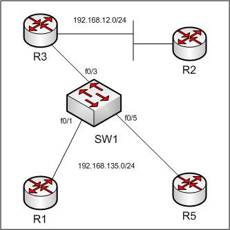
R2 is the RP and will be sending multicast pings.
R3 is the PIM DR for the 192.168.135.0 segment.
We will prevent R5 from joining group 239.0.0.1.
To deny IGMP joins on a switch, we use the IGMP filter and profile commands.
First, create the profile:
SW1(config)#ip igmp profile 1
SW1(config-igmp-profile)#deny
SW1(config-igmp-profile)#range 239.0.0.1 239.0.0.5
SW1(config-igmp-profile)#exit
Then attach it to the port:
SW1(config)#int f0/5
SW1(config-if)#ip igmp filter 1
Now we can test by having R1 and R5 join a group in the range 239.0.0.1 - 239.0.0.5
R1(config)#int e0/0
R1(config-if)#ip igmp join-group 239.0.0.1
R5(config)#int e0/0
R5(config-if)#ip igmp join-group 239.0.0.1
Let's debug on SW1 and see what happens:
SW1#debug ip igmp filter
event debugging is on
SW1#
03:26:30: IGMPFILTER: igmp_filter_process_pkt(): checking group 239.0.0.1 from Fa0/5: deny
03:26:31: IGMPFILTER: igmp_filter_process_pkt() checking group from Fa0/3 : no profile attached
03:26:33: IGMPFILTER: igmp_filter_process_pkt() checking group from Fa0/1 : no profile attached
No let's check R3 for any joined groups:
R3#show ip igmp groups
IGMP Connected Group Membership
Group Address Interface Uptime Expires Last Reporter
239.0.0.1 Ethernet0/0 00:09:28 00:02:30 192.168.135.1
224.0.1.40 Ethernet0/1 00:29:57 00:02:09 192.168.23.2
224.0.1.40 Ethernet0/0 00:30:01 00:02:37 192.168.135.3
Just to make sure, we can verify that only R1 responds to pings:
R2#ping 239.0.0.1
Type escape sequence to abort.
Sending 1, 100-byte ICMP Echos to 239.0.0.1, timeout is 2 seconds:
Reply to request 0 from 192.168.135.1, 8 ms
R2#
Tuesday, December 9, 2008
L2protocol Tunneling - An STP Example
This is a short lab designed to help me get familiar with l2protocol tunneling, specifically tunneling STP. We are also going tunnel CDP and VTP. What's neat about this is that we will alter the STP topology without using priority or changing mac addresses. Also, SW1 will see two switches as CDP neighbors on one port.
Here is the topolgy:

Currently SW4 is root with SW2 is blocking f0/16. This works best with SW4 or SW3 as root.
SW2# show spanning-tree blockedports
Name Blocked Interfaces List
-------------------- ------------------------------------
VLAN0001 Fa0/16
Number of blocked ports (segments) in the system : 1
We can use l2protocol tunneling to create a logical loop between SW1, SW3 and SW4 and force the link between SW3 and SW4 to block. Logically that would look like this:

Physically we would have this, with SW2 not being a part of the VTP domain, any CDP relationship or STP topology:

This might be a practical case where SW2 was a service provider switch/cloud. SW1, SW3, and SW4 would then be remote switches with SW3 and SW4 having a backdoor connection.
Now for the configuration. SW1, SW3 and SW4 configure their links as trunks:
SW1(config)#int f0/13
SW1(config-if)#sw t e d
SW1(config-if)#sw mo t
SW1(config-if)#no shut
Repeat this on ports f0/16 and f0/19 of SW3 and SW4. SW2 has the following configuration:
SW2(config-if)#int rang f0/13, f0/16, f0/19
SW2(config-if-range)#swit mode dot1q-tunnel
SW2(config-if-range)#l2protocol-tunnel cdp
SW2(config-if-range)#l2protocol-tunnel stp
SW2(config-if-range)#l2protocol-tunnel vtp
Now let's verify some things. First, we can see SW3 and SW4 as CDP neighbors to SW1:
SW1#show cdp ne | be De
Device ID Local Intrfce Holdtme Capability Platform Port ID
SW4 Fas 0/13 156 S I WS-C3550-2Fas 0/16
SW3 Fas 0/13 158 S I WS-C3550-2Fas 0/16
R1 Fas 0/1 129 R S I 3640 Eth 0/0
SW1#
Notice they are both on interface f0/13. Now let's see who's blocking between SW3 or SW4:
SW3# show spanning-tree blockedports | be VLAN
VLAN0001 Fa0/19
Number of blocked ports (segments) in the system : 1
SW3#
SW3 is blocking the connection between SW4. Perfect, just what we wanted.
This lab is designed as a little confidence booster. L2protocol tunneling is one of my weaknesses. I think because I recognize how complex it can get and it makes me worry (Ever since doing IPexpert V10 Volume 1 Lab 5). Practicing labs like this can help build confidence and gain familiarity with the configurations as well.
Here is the topolgy:

SW2# show spanning-tree blockedports
Name Blocked Interfaces List
-------------------- ------------------------------------
VLAN0001 Fa0/16
Number of blocked ports (segments) in the system : 1
We can use l2protocol tunneling to create a logical loop between SW1, SW3 and SW4 and force the link between SW3 and SW4 to block. Logically that would look like this:


Now for the configuration. SW1, SW3 and SW4 configure their links as trunks:
SW1(config)#int f0/13
SW1(config-if)#sw t e d
SW1(config-if)#sw mo t
SW1(config-if)#no shut
Repeat this on ports f0/16 and f0/19 of SW3 and SW4. SW2 has the following configuration:
SW2(config-if)#int rang f0/13, f0/16, f0/19
SW2(config-if-range)#swit mode dot1q-tunnel
SW2(config-if-range)#l2protocol-tunnel cdp
SW2(config-if-range)#l2protocol-tunnel stp
SW2(config-if-range)#l2protocol-tunnel vtp
Now let's verify some things. First, we can see SW3 and SW4 as CDP neighbors to SW1:
SW1#show cdp ne | be De
Device ID Local Intrfce Holdtme Capability Platform Port ID
SW4 Fas 0/13 156 S I WS-C3550-2Fas 0/16
SW3 Fas 0/13 158 S I WS-C3550-2Fas 0/16
R1 Fas 0/1 129 R S I 3640 Eth 0/0
SW1#
Notice they are both on interface f0/13.
SW3# show spanning-tree blockedports | be VLAN
VLAN0001 Fa0/19
Number of blocked ports (segments) in the system : 1
SW3#
SW3 is blocking the connection between SW4. Perfect, just what we wanted.
This lab is designed as a little confidence booster. L2protocol tunneling is one of my weaknesses. I think because I recognize how complex it can get and it makes me worry (Ever since doing IPexpert V10 Volume 1 Lab 5). Practicing labs like this can help build confidence and gain familiarity with the configurations as well.
Multicast Heartbeat - Generating SNMP Traps
This was a topic I ran into while browsing the multicast configuration guide today. I had dynamips up and running so I created a small lab.
Topology:
R1---R2---R5---R7
R1 is sending traffic to 225.0.0.7
R2 is the BSR/RP
R5 is will be configured for hearbeat
R7 has "ip igmp join-group 225.0.0.7" on one of its interfaces.
The commands to enable multicast heartbeat are very simple:
R5(config)#snmp-server host 9.9.9.9 traps public ipmulticast
R5(config)#snmp-server enable traps ipmulticast
R5(config)#ip multicast heartbeat 225.0.0.7 ?
<1-100> Minimal number of intervals where the heartbeats must be seen
R5(config)#ip multicast heartbeat 225.0.0.7 1 ?
<1-100> Number of intervals to monitor for heartbeat
R5(config)#ip multicast heartbeat 225.0.0.7 1 2 ?
<10-3600> Length of intervals in seconds
R5(config)#ip multicast heartbeat 225.0.0.7 1 2 10
R5(config)#
You will see this message:
R5#
*Mar 1 00:29:58.523: MHBEAT(0): Unless packets sent to 225.0.0.7 are seen in 1 out of 2 intervals of 10 seconds, an SNMP trap may be emitted.
Let's debug SNMP packets and the heartbeat so we can see the trap:
R5#debug snmp packets
SNMP packet debugging is on
R5#debug ip mhbeat
IP multicast heartbeat debugging is on
Now on R1 start sending packets, then stop:
R1#ping 225.0.0.7 re 2
Type escape sequence to abort.
Sending 10, 100-byte ICMP Echos to 225.0.0.7, timeout is 2 seconds:
Reply to request 0 from 150.100.56.7, 160 ms
Reply to request 1 from 150.100.56.7, 148 ms
R1#
Let's check R5. After a short while we see the following:
*Mar 1 00:38:48.555: MHBEAT(0): SNMP Trap for missing heartbeat
*Mar 1 00:38:48.575: SNMP: Queuing packet to 9.9.9.9
*Mar 1 00:38:48.575: SNMP: V1 Trap, ent ciscoExperiment.2.3.1, addr 150.100.56.5, gentrap 6, spectrap 1
ciscoIpMRouteHeartBeatEntry.2.225.0.0.7 = 0.0.0.0
ciscoIpMRouteHeartBeatEntry.3.225.0.0.7 = 10
ciscoIpMRouteHeartBeatEntry.4.225.0.0.7 = 2
ciscoIpMRouteHeartBeatEntry.5.225.0.0.7 = 0
*Mar 1 00:38:48.827: SNMP: Packet sent via UDP to 9.9.9.9
For reference, here is the link to the DocCD:
IP Multicast Heartbeat
Monday, December 8, 2008
PPP - Negotiated address via DHCP
This kind of task may seem more difficult than it really is. I, in fact, spent way too long one morning/afternoon/evening trying to get this scenario to work. Turns out my server did not have a route back to the requester's subnet. So here it is without all the crap (ok, some of it) I went through:
Topology:
R5---R2---R1
R5 to R2 is PPP.
R5 needs to negotiate its address.
R1 is to supply this address.
R2-R5: 150.100.25.x/24
R1-R2: 150.100.12.x/24
R5 config is EASY:
interface Serial0/1
ip address negotiated
R2 is also easy, we configure it's interface to supply the address via DHCP and then specify a DHCP server:
R2(config)#int s1/1
R2(config-if)#peer default ip address dhcp
R2(config-if)#exit
R2(config)# ip dhcp-server 150.100.12.1
On R1 we configure the pool and everything is cool, right?
R1(config)#ip dhcp pool R5
R1(dhcp-config)#network 150.100.25.0 /24
R1(dhcp-config)#exit
R1(config)#ip dhcp excluded-address 150.100.25.1 150.100.25.4
R1(config)#ip dhcp excluded-address 150.100.25.6 150.100.25.255
Let's check R5, to see if it got an address:
R5#show ip int brief | inc l1/1
Serial1/1 unassigned YES IPCP up up
Nothing! Let's do some debugging on R1 with an ACL to match DHCP packets:
R1(config)#access-list 150 pe udp any any eq bootpc
R1(config)#access-list 150 pe udp any any eq bootps
R1(config)#access-list 150 pe udp any eq bootpc any
R1(config)#access-list 150 pe udp any eq bootps any
R1#debug ip packet 150 detail
IP packet debugging is on (detailed) for access list 150
*Mar 1 00:15:27.995: IP: s=150.100.12.1 (local), d=150.100.25.2, len 328, unroutable
*Mar 1 00:15:27.999: UDP src=67, dst=67
R1 has no route to 150.100.25.0/24 yet! Let's configure one and then manually shut/no shut the interface on R5:
R1(config)#ip route 150.100.25.0 255.255.255.0 150.100.12.2
R1#debug ip dhcp server events
*Mar 1 00:19:27.263: DHCPD: Sending notification of DISCOVER:
*Mar 1 00:19:27.263: DHCPD: htype 1 chaddr 0000.0c07.79e1
*Mar 1 00:19:27.267: DHCPD: circuit id 00000000
*Mar 1 00:19:27.267: DHCPD: Seeing if there is an internally specified pool class:
*Mar 1 00:19:27.271: DHCPD: htype 1 chaddr 0000.0c07.79e1
*Mar 1 00:19:27.271: DHCPD: circuit id 00000000
*Mar 1 00:19:28.411: DHCPD: Adding binding to radix tree (150.100.25.5)
*Mar 1 00:19:28.415: DHCPD: Adding binding to hash tree
*Mar 1 00:19:28.419: DHCPD: assigned IP address 150.100.25.5 to client 0063.6973.636f.2d31.3530.2e31.3030.2e32.352e.322d.5365.7269.616c.312f.31.
*Mar 1 00:19:28.495: DHCPD: Sending notification of ASSIGNMENT:
*Mar 1 00:19:28.499: DHCPD: address 150.100.25.5 mask 255.255.255.0
*Mar 1 00:19:28.499: DHCPD: htype 1 chaddr 0000.0c07.79e1
*Mar 1 00:19:28.503: DHCPD: lease time remaining (secs) = 86400
*Mar 1 00:20:17.647: DHCPD: checking for expired leases.
*Mar 1 00:22:17.647: DHCPD: checking for expired leases.
*Mar 1 00:24:17.647: DHCPD: checking for expired leases.
Now check R5:
R5#show ip int bri s1/1
Interface IP-Address OK? Method Status Protocol
Serial1/1 150.100.25.5 YES IPCP up up
R5#
*** IMPORTANT ***
R1 needs a route back to the 150.100.25.0/24 subnet. In this case I have a default route from R1 toward R2. This is EXTREMELY important. I wasted many minutes of my life trying to get this thing to come up. My DHCP configuration was correct but the DHCP server did not have a route back to the requester!
Two vlans, One Port, No trunk
I recall a task somewhere I don't remember where we needed two vlans on one port but no trunk...in this case you can use a voice vlan for your second vlan. It is very easy to test:
Topology:
R1---SW1---SW2---R2
R1's interface:
interface Ethernet0/0
interface Ethernet0/0.2
encapsulation dot1Q 2
ip address 139.1.2.101 255.255.255.0
SW1:
interface FastEthernet0/1
switchport access vlan 11
switchport voice vlan 2
SW2:
SW2#show cdp ne | in R2
R2 Fas 0/2 135 R S I 3640 Eth 0/0
SW2#
Rack1SW2#show run int f0/2
Building configuration...
Current configuration : 83 bytes
!
interface FastEthernet0/2
switchport access vlan 2
switchport mode access
So let's ping from R1 to R2 (139.1.2.2)
Rack1R1#ping 139.1.2.2
Type escape sequence to abort.
Sending 5, 100-byte ICMP Echos to 139.1.2.2, timeout is 2 seconds:
!!!!!
Success rate is 100 percent (5/5), round-trip min/avg/max = 4/4/4 ms
R1#
IPv6 - Stateless autoconfig
Logical Topology:
R6------SW2
R6 is in vlan 6.
SW2 get its address for SVI 6 via stateless autoconfiguration.
R6 will be advertising the prefix for SW2 to use to build it's address.
R6 already has an IPv6 address configured: 2001:cc1e:1:6::6/64
Also, a good command to run here is "debug ipv6 nd".
Rack1R6#debug ipv6 nd
ICMP Neighbor Discovery events debugging is on
Rack1SW2#debug ipv6 nd
ICMP Neighbor Discovery events debugging is on
Before we do anything let's see what debugging gives us on R6:
Rack1R6#
*Mar 1 00:42:14.219: ICMPv6-ND: Sending RA to FF02::1 on Ethernet0/1
*Mar 1 00:42:14.219: ICMPv6-ND: MTU = 1500
*Mar 1 00:42:14.219: ICMPv6-ND: prefix = 2001:CC1E:1:6::/64 onlink autoconfig
*Mar 1 00:42:14.219: ICMPv6-ND: 2592000/604800 (valid/preferred)
Rack1R6#
We can see that R6 is already advertising it's prefix for hosts on this segment to use. Look at the output of the debug. We have
1) All nodes multicast address FF02::1, this is the destination of the RA advertisement
2) MTU of 1500
3) Prefix advertised by R6 2001:CC1E:1:6::/64
4) Valid and Preferred Lifetime 2592000/604800
All we need to do on SW2 is configure the SVI for autoconfiguration:
SW2#conf t
SW2(config)#int vlan 6
SW2(config-if)#ipv6 address ?
WORD General prefix name
X:X:X:X::X IPv6 link-local address
X:X:X:X::X/<0-128> IPv6 prefix
autoconfig Obtain address using autoconfiguration
SW2(config-if)#ipv6 address autoconfig
Notice that SW2 immediately sends an RS message asking for information about this segment:
00:19:39: ICMPv6-ND: Sending RS on Vlan6
00:19:39: ICMPv6-ND: Received RA from FE80::205:32FF:FE22:E442 on Vlan6
00:19:39: ICMPv6-ND: Sending NS for 2001:CC1E:1:6:21D:45FF:FEC0:F443 on Vlan6
00:19:39: ICMPv6-ND: Autoconfiguring 2001:CC1E:1:6:21D:45FF:FEC0:F443 on Vlan6
00:19:40: ICMPv6-ND: DAD: 2001:CC1E:1:6:21D:45FF:FEC0:F443 is unique.
00:19:40: ICMPv6-ND: Sending NA for 2001:CC1E:1:6:21D:45FF:FEC0:F443 on Vlan6
00:19:40: ICMPv6-ND: Address 2001:CC1E:1:6:21D:45FF:FEC0:F443/64 is up on Vlan6
It also receives the prefix, calcualtes its global unicast address and performs DAD. Now let's check the interface on SW2:
SW2#show ipv6 interface
Vlan6 is up, line protocol is up
IPv6 is enabled, link-local address is FE80::21D:45FF:FEC0:F443
Global unicast address(es):
2001:CC1E:1:6:21D:45FF:FEC0:F443, subnet is 2001:CC1E:1:6::/64 [PRE]
valid lifetime 2591864 preferred lifetime 604664
Joined group address(es):
FF02::1
FF02::2
FF02::1:FFC0:F443
MTU is 1500 bytes
ICMP error messages limited to one every 100 milliseconds
ICMP redirects are enabled
ND DAD is enabled, number of DAD attempts: 1
ND reachable time is 30000 milliseconds
ND advertised reachable time is 0 milliseconds
ND advertised retransmit interval is 0 milliseconds
ND router advertisements are sent every 200 seconds
ND router advertisements live for 1800 seconds
ND advertised default router preference is Medium
Hosts use stateless autoconfig for addresses.
Rack1SW2#
There are several adjustments we can make on the timers. Let's look at R6:
R6(config-if)#ipv6 nd ?
advertisement-interval Send an advertisement interval option in RA's
dad Duplicate Address Detection
managed-config-flag Hosts should use DHCP for address config
ns-interval Set advertised NS retransmission interval
other-config-flag Hosts should use DHCP for non-address config
prefix Configure IPv6 Routing Prefix Advertisement
ra-interval Set IPv6 Router Advertisement Interval
ra-lifetime Set IPv6 Router Advertisement Lifetime
reachable-time Set advertised reachability time
suppress-ra Suppress IPv6 Router Advertisements
Here we can set various parameters such as the advertisement interval (200 seconds default) and the RA lifetime.
More information on these options can be found in the addressing section non the IPv6 configuration guide on the DocCD:
Implementing IPv6 Addressing and Basic Connectivity
Saturday, December 6, 2008
BGP - fast-external-fallover
This feature allows the router to bring a BGP session down when the interface to that peer goes down. If you don't want this or are asked to not allow this to happen, you can disable it:
R1 has a neighbor:
R1#show ip bgp sum | be Ne
Neighbor V AS MsgRcvd MsgSent TblVer InQ OutQ Up/Down State/PfxRcd
136.10.12.2 4 200 188 188 38 0 0 01:56:59 4
R1(config)#int f0/0
R1(config-if)#shut
*Dec 7 03:16:21.270: %BGP-5-ADJCHANGE: neighbor 136.10.12.2 Down Interface flap
We can prevent R1 from tearing the session down by disabling fast-external-fallover:
R1#show ip bgp sum | be Ne
Neighbor V AS MsgRcvd MsgSent TblVer InQ OutQ Up/Down State/PfxRcd
136.10.12.2 4 200 196 194 50 0 0 00:00:03 4
R1(config)#router bgp 100
R1(config-router)#no bgp fast-external-fallover
R1(config-router)#int f0/0
R1(config-if)#shut
R1(config-if)#
*Dec 7 03:19:41.386: %LINK-5-CHANGED: Interface FastEthernet0/0, changed state to administratively down
*Dec 7 03:19:42.386: %LINEPROTO-5-UPDOWN: Line protocol on Interface FastEthernet0/0, changed state to down
R1(config-if)#^Z
R1#show ip bgp sum | be Ne
Neighbor V AS MsgRcvd MsgSent TblVer InQ OutQ Up/Down State/PfxRcd
136.10.12.2 4 200 196 194 54 0 0 00:00:50 4
Still up:
R1#show ip bgp sum | be Ne
Neighbor V AS MsgRcvd MsgSent TblVer InQ OutQ Up/Down State/PfxRcd
136.10.12.2 4 200 196 195 54 0 0 00:01:29 4
Now the session will come down when the hold time expires. Some things to remember:
-Only works for directly-connected EBGP peers (hence the word "external" in the command)
-I tested with ebgp-multihop peers and it does not have any effect
-Keepalives are use to bring session down
-Also configurable per-interface with ip bgp fast-external-fallover
IPexpert Volume 2 Section 13 Review - PART I
Well I am 2/3 of the way done here with a couple hours to go, but I am going to finish this next week. I have a terrible cold or something...I don't know, maybe it's all the Hot Pockets I ate this week. Whatever it is...I AM DEFEATED for the day.
I semi-graded this thing and I must say this is the TRICKIEST/HARDEST lab of them all. There are a total of 58 tasks, each worth 1 or 2 points and a few worth 3. This is the longest lab I have ever done to date. I am not entirely sure I would have finished in 8 hours...if I did, I wouldn't have been able to grade or verify much.
I think I missed about 7 or 8 tasks for about 15 or so points so far. Definitely a failed effort, but there were some good lessons learned. Here is a summary of what I had to configure:
-Fallback bridging. I actually got this right
-Only allow NetBIOS over TCP/IP in vlan 999. Used a VACL but I didn't what ports to match for netbios. I used range 135 - 139 but I don't know if this is right.
-Make sure CAT1 never becomes root for VLAN 999. The PG disabled STP for this VLAN, I used bpdufilter on the ports in VLAN 999. The PG was probably more correct.
-If R4 detects PVC states other than invalid, active or inactive - notify the trap receiver. What traps are these??
-Then there was a task that had me configure a secondary address 192.168.80.33/27 on an interface that already belonged to 192.168.80.0/24. Then you were supposed to filter out RIP routes on this subnet - HUH? I have no idea if this was a typo or what but the PG was really bad at explaining this one. I am not going into more detail - see it for yourself :-)
-OSPF task that had two different authentication keys on the same interface. This was a little tricky but I got it to work. I remember seeing this on GS so that helped a lot. You had to use neighbor statements on the spokes instead of the hub.
Anyways. this lab is truly a mind-number. Just the kind of trickery to expect on the lab, I assume. If you think you are hot stuff - try this one ;-)
Subscribe to:
Posts (Atom)

